A plastic pipe extruder is not simply a motor pushing melted plastic through a die. It is a coordinated production system in which feeding, melting, conveying, filtration, shaping, cooling, and haul-off must work together. If one component is poorly selected or incorrectly matched, the result can be unstable output, inconsistent wall thickness, surface defects, dimensional variation, or unnecessary energy consumption.
For manufacturers evaluating a new plastic pipe production line, understanding the key components of a plastic pipe extruder is essential before comparing machine prices. A lower-cost extruder may look attractive, but the real investment decision should be based on output stability, material compatibility, pipe specifications, operating cost, and the reliability of the complete line.
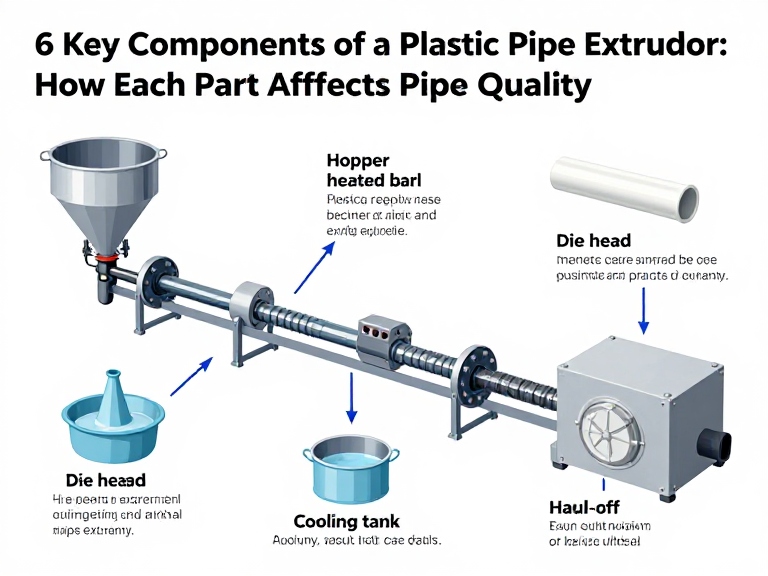
The six core components of a typical plastic pipe extrusion system are the feeding system, extruder screw and barrel, drive and heating system, screen changer and melt filtration assembly, extrusion die head, and downstream sizing, cooling, and haul-off equipment. Together, they meter raw material, melt and homogenize the polymer, remove contaminants, form the pipe, control its dimensions, and pull it through the production line at a stable speed. The exact configuration depends on the polymer, pipe diameter, wall thickness, production capacity, and required quality standard.
The most important components of a plastic pipe extruder perform different but interdependent jobs:
Feeding system: Delivers a consistent quantity of resin, compound, or prepared material into the extruder.
Screw and barrel: Convey, compress, melt, mix, and homogenize the polymer.
Drive and heating system: Supplies the mechanical energy and controlled heat required for stable extrusion.
Screen changer and filtration: Retain contaminants and help protect the die and finished pipe, where the process requires melt filtration.
Die head: Shapes the molten polymer into a continuous pipe profile.
Downstream equipment: Calibrates, cools, pulls, measures, and cuts the pipe to the required dimensions and length.
One important distinction: the first five items are commonly integrated into or directly associated with the extruder, while sizing, cooling, haul-off, and cutting equipment are downstream parts of the complete pipe extrusion line. Buyers should evaluate the whole system, not just the main extruder unit.
| Component | Main function | What to evaluate | Effect on production |
|---|---|---|---|
| Feeding system | Controls raw-material delivery | Feeder type, dosing accuracy, material flow, moisture control where required | Stable feed rate and consistent output |
| Screw and barrel | Conveys, melts, mixes, and pressurizes polymer | Screw geometry, L/D ratio, material compatibility, wear resistance | Melt quality, throughput, and process stability |
| Drive and heating system | Provides rotation and thermal control | Motor capacity, gearbox, torque, heater zones, temperature sensors | Stable processing and operating efficiency |
| Screen changer and filtration | Filters contaminants from the melt when required | Screen specification, pressure rating, changeover method | Protection of the die and reduced contamination risk |
| Die head | Forms the pipe profile | Flow channel design, die dimensions, mandrel, material distribution | Wall thickness, concentricity, and surface finish |
| Downstream system | Sizes, cools, pulls, and cuts the pipe | Vacuum calibration, cooling capacity, haul-off grip, cutting accuracy | Final dimensions, straightness, and finished length |
The feeding system supplies polymer material to the extruder at a controlled rate. Depending on the line design, the material may be supplied as pellets, granules, regrind, powder, or a prepared compound. The feeder must match the material's physical characteristics and the production process.
Raw material is stored in a hopper or material-loading system and transferred into the extruder throat. A simple gravity-fed hopper may be sufficient for some free-flowing pellets. More demanding applications may require volumetric or gravimetric dosing to control the amount of material entering the screw.
Volumetric feeders regulate material based on volume over time. Gravimetric systems measure material by weight and can compensate for changes in bulk density, making them useful where dosing accuracy and formulation consistency are important. The correct choice depends on whether the line processes a single resin or a controlled blend of polymers, additives, colorants, and recycled content.
Unstable feeding can cause output fluctuations even when the screw, barrel, and die are correctly designed. Variations in material delivery may affect melt pressure, pipe dimensions, wall thickness, and line stability. Bridging, poor flow, inconsistent pellet size, or excessive dust can also interrupt production.
For PVC pipe production, the material is often supplied as a formulated dry blend rather than ordinary resin pellets. The feeding and conveying arrangement must therefore be designed around the compound's flow behavior and the extruder's requirements. PE and PP systems commonly use pelletized feedstock, although additives and regrind can change the feeding requirements.
Whether the feeder is suitable for the actual resin or compound.
Whether dosing accuracy meets the formulation requirements.
Whether the hopper and conveying system prevent material bridging or segregation.
Whether drying or moisture control is required for the selected material.
Whether the supplier can demonstrate stable feeding at the target production rate.
Our recommendation is to provide the manufacturer with the exact material formulation and expected feed condition. Do not approve a feeder based only on its nominal capacity. A system that handles virgin pellets well may behave differently with powder, regrind, or blended compounds.
The screw and barrel assembly is the central processing unit of a plastic pipe extruder. The screw rotates inside the heated barrel, conveying material forward while applying mechanical work and controlling the polymer's melting and mixing process.
A conventional single-screw extruder screw is commonly divided into functional zones:
Feed zone: Receives and conveys solid material from the feed throat.
Compression or transition zone: Compresses the material and supports melting as the available channel volume changes.
Metering zone: Delivers a more uniform melt toward the die under controlled pressure and flow conditions.
The barrel provides the enclosed processing channel and supports heating and temperature measurement. The screw geometry, channel depth, compression ratio, length-to-diameter ratio, and surface condition all influence processing behavior.
For many conventional PE and PP pipe applications, single-screw extruders are widely used because they provide a practical balance of throughput, process simplicity, and operating cost. PVC pipe production often uses conical or parallel twin-screw extruders, particularly where controlled feeding, mixing, and thermal processing of PVC compound are required.
There is no universal winner. The correct machine depends on the polymer, formulation, output target, pipe size range, and processing window. Buying a twin-screw machine simply because it appears more advanced is not a sound investment if a properly configured single-screw system meets the production requirement. Equally, choosing a basic single-screw unit for a formulation that needs stronger mixing or controlled compounding can create persistent quality problems.
Correct screw geometry for the selected polymer and formulation.
Suitable barrel and screw materials for wear and corrosion conditions.
Consistent machining and appropriate surface finish.
A design that supports the required output without excessive shear or unstable melt conditions.
Practical access for maintenance and inspection.
For manufacturers processing abrasive fillers, recycled feedstock, or demanding compounds, wear resistance deserves particular attention. A cheaper screw that wears rapidly can lead to declining output, longer residence time, inconsistent melt quality, and expensive replacement downtime.
The drive system rotates the screw, while the heating and cooling arrangements help maintain the processing temperature. These systems are often treated as supporting equipment, but their performance directly affects production stability and energy use.
The motor supplies power to rotate the screw. The gearbox reduces speed and increases torque to suit the extrusion process. Couplings, bearings, and transmission components transfer the mechanical load. The drive must handle the required torque across the operating range, including start-up and changes in material conditions.
When comparing machines, do not judge the drive by motor power alone. A high-power motor does not automatically guarantee stable output. Buyers should also review gearbox design, torque capacity, speed control, mechanical protection, and the manufacturer's stated operating range.
Barrel heaters bring the machine to its operating temperature and help maintain separate thermal zones. Temperature sensors monitor each zone, while the control system adjusts heating output. Depending on the extruder design, fans or other cooling arrangements may remove excess heat.
In plastic extrusion, temperature control is not simply a matter of making the barrel hotter. The material must reach a suitable melt condition without unnecessary thermal degradation. Excessive heat can damage heat-sensitive polymers, while insufficient heat can cause poor melting, high pressure, unstable flow, or surface defects.
Number and arrangement of independently controlled heating zones.
Temperature sensor accuracy and placement.
Drive motor and gearbox suitability for the intended screw load.
Speed control range and stability.
Alarm, overload, and protection functions.
Energy consumption under realistic production conditions.
For commercial users, we recommend requesting operating data at the target material and output rather than relying on a maximum power rating. The useful question is not how much power the machine can consume, but whether the drive and thermal system can maintain the required process window efficiently.
A screen changer holds a filter screen or screen pack in the melt flow path. It is used to retain foreign particles and contaminants before the polymer reaches the die. Depending on the material and process, filtration can protect downstream components and reduce visible defects caused by contamination.
The molten polymer passes through one or more layers of mesh or a specified filter medium. Contaminants larger than the effective openings are retained, while the melt continues toward the die. As material accumulates on the screen, pressure upstream of the filter can rise. The screen must therefore be monitored and replaced or cleaned according to the system design and process requirements.
For clean, controlled virgin resin, the filtration requirement may be different from a line using recycled material or a formulation that carries a higher contamination risk. Recycled feedstock generally requires careful assessment of incoming material quality and filtration needs. A screen changer is not a substitute for proper raw-material control.
Manual screen changers may be adequate for some lower-output or less demanding processes. Hydraulic or continuous screen-changing systems can reduce interruptions in applications where screen replacement would otherwise cause significant downtime. The best choice depends on contamination level, melt pressure, production rate, and the cost of stopping the line.
Maximum operating pressure and compatibility with the extruder.
Screen mesh specification and available filter area.
Ease and safety of screen replacement.
Whether screen changes interrupt production.
Pressure monitoring and maintenance access.
Suitability for the actual material and contamination level.
Do not specify an excessively fine screen without checking its effect on pressure and throughput. Filtration should be matched to the contamination risk and process capability. A poorly selected screen can create pressure instability and unnecessary maintenance.
The die head distributes molten polymer around a mandrel and shapes it into a continuous tubular profile. It is one of the most influential components for finished pipe geometry. Even a capable extruder can produce poor pipe if the die is incorrectly designed, assembled, adjusted, or maintained.
Molten polymer enters the die head and flows through internal channels around the mandrel. The annular gap between the die and mandrel establishes the initial pipe geometry. The melt exits as a continuous tube, which is then calibrated and cooled downstream.
Die design must support even circumferential melt distribution. If flow is uneven, the pipe may show inconsistent wall thickness or eccentricity. Die temperature, melt pressure, material behavior, centering, and flow-channel design all contribute to the result.
Die and mandrel dimensions: Must match the target pipe range and process design.
Flow channel geometry: Influences melt distribution and pressure behavior.
Centering adjustment: Helps align the die and mandrel to control wall thickness uniformity.
Temperature control: Supports stable melt flow through the die.
Material and surface finish: Affect wear, cleaning, and polymer flow behavior.
A line designed for small-diameter pipe does not automatically cover large-diameter production simply by changing a few settings. Pipe diameter range, wall thickness, material, output, and downstream calibration capacity must be considered together. A die head that is difficult to clean or adjust can also increase changeover time and make consistent production harder.
When requesting a quotation, provide the full diameter range and wall-thickness requirements. Ask the manufacturer how many die sets, mandrels, or calibration tools are included and which additional tooling must be purchased separately.
The downstream equipment is sometimes overlooked when buyers focus on the extruder's screw diameter or motor power. That is a mistake. The pipe leaving the die is still hot and dimensionally unstable. It must be calibrated, cooled, pulled at a controlled speed, and cut accurately.
For many thermoplastic pipe lines, vacuum calibration helps control the outside diameter as the pipe enters the sizing section. The calibration sleeve or tank establishes the required external dimensions while the material begins to solidify. The design must match the pipe size and material process.
For certain products and production methods, sizing arrangements differ. Buyers should confirm the calibration method offered for their specific pipe type rather than assume every plastic pipe line uses identical equipment.
Cooling removes heat from the extruded pipe so that it can retain its shape during haul-off and cutting. Cooling capacity, water circulation, tank length, spray or immersion arrangement, and temperature management all influence production stability.
Insufficient or uneven cooling can contribute to deformation, dimensional drift, or problems during cutting. Excessively aggressive cooling may also create process issues depending on the material and product design. Cooling should be engineered as part of the overall line speed and pipe specification.
The haul-off pulls the pipe through the calibration and cooling sections at a controlled speed. Belt, caterpillar, or other gripping arrangements are selected according to pipe diameter, surface, and production requirements.
Haul-off speed must be coordinated with extruder output. If pulling speed changes without corresponding control of melt output, wall thickness and dimensions can shift. The grip must also be sufficient to move the pipe without marking, flattening, or damaging its surface.
The cutting unit produces pipe sections at the required length. Depending on the application, the line may use saw cutting, planetary cutting, or another suitable method. The system should coordinate with the moving pipe and avoid excessive burrs, deformation, or rough cut ends.
For commercial production, automatic length measurement and synchronized cutting can reduce manual handling and improve consistency. However, the cutting method must be appropriate for the pipe diameter, wall thickness, material, and required end finish.
| Production priority | Most influential components | Typical risk if poorly matched | Practical buying advice |
|---|---|---|---|
| Stable material delivery | Feeder, hopper, material handling | Surging, inconsistent output, formulation variation | Test with the actual resin or compound |
| Melt quality and throughput | Screw, barrel, drive, heating | Poor plasticization, overheating, unstable pressure | Match screw design and drive to polymer and output |
| Contamination control | Screen changer and filtration | Die blockage, inclusions, surface defects | Specify filtration based on feedstock cleanliness |
| Wall thickness and pipe geometry | Die head, mandrel, calibration | Eccentric wall, dimensional variation | Review tooling and adjustment capability |
| Final dimensions and productivity | Cooling, haul-off, cutting | Deformation, inaccurate lengths, line stoppages | Evaluate the complete downstream line capacity |
| Advantages | Limitations and trade-offs |
|---|---|
| Integrated components can be matched to a defined pipe specification. | A complete line requires a higher initial investment than purchasing only the extruder. |
| Coordinated controls can improve production stability and reduce manual adjustment. | Control integration and commissioning require experienced technical support. |
| Dedicated tooling can support repeatable pipe dimensions across planned product ranges. | Additional dies, mandrels, and calibration tools may increase the total project cost. |
| Automatic haul-off and cutting can reduce labor and handling requirements. | Automation adds maintenance requirements and depends on correct setup. |
| A properly specified line can support consistent commercial production. | Performance still depends on material quality, operator skill, maintenance, and process control. |
Pipe quality is the combined result of material preparation, melt processing, die design, calibration, cooling, and handling. It is rarely useful to blame one component without checking the entire process.
Uneven wall thickness can be related to die and mandrel centering, melt distribution, unstable feeding, pressure fluctuations, or inconsistent haul-off speed. Start by checking whether the variation is circumferential, longitudinal, or both. That pattern can help narrow down the likely source.
Surface defects may be caused by contamination, poor plasticization, unsuitable temperature settings, excessive shear, die deposits, or material inconsistency. Check the feedstock and filtration condition before making large temperature adjustments. Increasing heat without identifying the cause can make some problems worse.
Outside diameter variation may indicate inconsistent calibration, vacuum instability, uneven cooling, changes in line speed, or insufficient coordination between extrusion output and haul-off. Confirm the calibration sleeve condition and the stability of the vacuum and cooling systems.
Low output can result from screw design, motor and gearbox limits, feed instability, melt pressure, die resistance, or downstream capacity. A larger motor alone will not necessarily solve the problem. The production bottleneck may be the die, cooling system, or haul-off rather than the extruder.
| Observed problem | Possible causes | Recommended first checks |
|---|---|---|
| Output surging | Inconsistent feeding, material bridging, screw or process instability | Inspect feeder flow, material condition, screw speed, and melt pressure trends |
| Uneven wall thickness | Die misalignment, uneven melt flow, unstable output or haul-off | Check die centering, circumferential wall measurements, and line synchronization |
| Surface roughness | Contamination, poor melting, unsuitable temperature, die deposits | Inspect raw material, screen condition, temperature profile, and die surface |
| Pipe deformation | Insufficient cooling, unstable calibration, excessive pulling force | Review vacuum, cooling capacity, haul-off grip, and pipe temperature |
| Frequent screen blockage | Contaminated feedstock, unsuitable screen specification | Check incoming material cleanliness and filtration selection |
| Inaccurate cutting length | Measurement or synchronization problems, sensor faults | Verify encoder, length settings, cutting synchronization, and calibration |
These are diagnostic starting points, not guaranteed causes. Change one process variable at a time where practical and record the result. Uncontrolled adjustments make it difficult to identify the actual fault and can introduce new defects.
Before requesting quotations, prepare a product and production brief. Suppliers cannot make a meaningful recommendation from the phrase “plastic pipe extrusion machine” alone.
Pipe material: PVC, PE, PP, or another polymer.
Minimum and maximum outside diameter.
Required wall thickness and dimensional tolerances.
Pipe application, such as water supply, drainage, conduit, or industrial use.
Required output per hour or per shift.
Applicable product standards and destination-market requirements.
Ask for a component-by-component quotation. Confirm the extruder model, feeder, screw and barrel specification, die tooling, vacuum sizing or calibration equipment, cooling tanks, haul-off, cutting machine, control system, and any stacking or handling equipment.
Do not assume a quoted “production line” includes all necessary tooling. Some suppliers quote the main machine and list dies, calibration sleeves, spare parts, or auxiliary equipment separately.
Request the expected output for your specific material, pipe diameter, and wall thickness. Ask what conditions the quoted capacity assumes. Maximum output figures are not directly comparable if suppliers use different polymers, pipe dimensions, or quality criteria.
Where possible, request a production demonstration or documented reference for a comparable pipe specification. A machine's nominal capacity is less valuable than its ability to maintain acceptable dimensions and surface quality at the required operating rate.
Confirm installation support, operator training, troubleshooting assistance, spare-parts availability, warranty coverage, and expected response times. For a production facility, downtime can cost more than a modest difference in machine purchase price.
Include purchase price, tooling, installation, electricity, cooling water, compressed air where required, labor, maintenance, consumables, spare parts, and expected downtime. A line with a lower initial price may have a higher operating cost if it requires frequent manual intervention or has limited process stability.
This is one of the most important configuration decisions, particularly for buyers choosing between PE, PP, and PVC pipe production systems.
| Factor | Single-screw extruder | Twin-screw extruder |
|---|---|---|
| Typical applications | Commonly used for PE and PP pipe extrusion | Commonly used for PVC pipe compounds and other processes requiring specific mixing or feeding behavior |
| Processing approach | Conveys, melts, and homogenizes material through one rotating screw | Uses two screws with a configuration selected for conveying, mixing, and processing needs |
| Material handling | Well suited to many pelletized thermoplastics | Can be advantageous for certain formulated materials, including PVC compounds |
| Investment and maintenance | Often a simpler and more economical configuration for suitable applications | May involve a higher initial cost and more specialized configuration |
| Selection priority | Choose when it meets the polymer, output, and product requirements | Choose when the material formulation and process justify the configuration |
We recommend selecting the screw configuration from the material and product specification—not from a general belief that one type is always better. For PVC, confirm that the proposed extruder is designed for the actual compound and its thermal processing requirements. For PE or PP, evaluate screw design, output stability, and energy consumption under the target operating conditions.
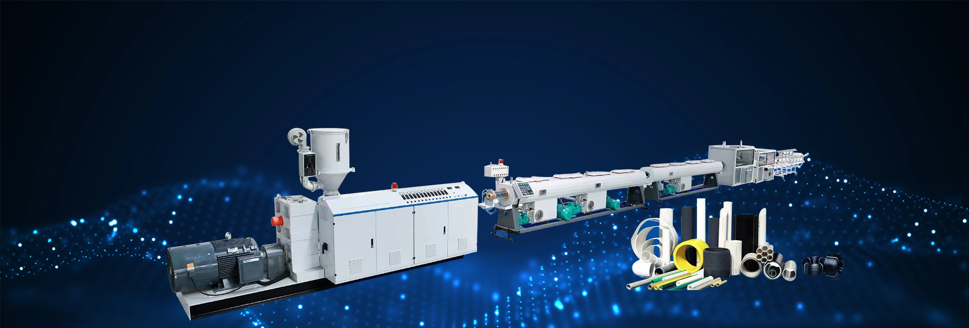
XJGMACHINE offers plastic processing equipment for a range of manufacturing applications, from compounding to thermoforming. Its equipment portfolio is positioned around durability, production efficiency, and practical operation for modern plastic processing facilities.
For buyers planning a new pipe manufacturing project, the most useful starting point is to share the intended polymer, pipe diameter range, wall thickness, required output, and production environment. These details allow the supplier to assess the required extruder configuration and supporting equipment instead of recommending a generic machine.
Plastic pipe manufacturing may also form part of a wider processing operation. For example, a facility handling production scrap or rejected plastic parts may need size-reduction equipment. A plastic crusher can be relevant for suitable scrap preparation, while a single shaft shredder or double shaft shredder may be considered for different feed sizes and material handling requirements. These machines are auxiliary recycling equipment, not substitutes for the pipe extruder itself.
Where recovered plastic is intended for reuse, the material preparation process must be evaluated carefully. A suitable PE/PP pelletizing and granulating line may be relevant to converting appropriate prepared material into pellets, but the recycled feedstock still needs to meet the pipe manufacturer's material and quality requirements.
Buyers with additional finishing requirements may also consider a plastic pipe laser printer for product identification and marking, or a PVC pipe bending machine for compatible downstream processing applications. These should be specified according to the final product and production workflow.
Not every factory needs to replace its entire extrusion line. If the current machine is mechanically sound, a targeted upgrade may deliver a better return. The key is to identify the actual production bottleneck before purchasing new equipment.
If material delivery fluctuates or operators frequently intervene to clear bridging, review the hopper, material handling, and dosing arrangement. Better feeding control may improve consistency without replacing the main extruder.
If output has declined over time, pressure behavior has changed, or the screw and barrel show significant wear, inspect the processing assembly. A replacement screw should be designed for the actual polymer and operating conditions rather than selected only by matching its external dimensions.
Improved temperature monitoring, drive control, pressure measurement, and line synchronization can make the process easier to manage. However, adding automation will not fix a fundamentally unsuitable die or poor material quality.
If the extruder can produce melt at the required rate but the line cannot maintain dimensions or cut accurately, the limitation may be in calibration, cooling, haul-off, or cutting. Review the full line before investing in a larger extruder.
The main components associated with a plastic pipe extruder include the feeding system, screw and barrel, drive and heating system, screen changer or melt filtration assembly, and die head. A complete pipe extrusion line also includes sizing, cooling, haul-off, and cutting equipment.
The screw and barrel are central to conveying, melting, and homogenizing the polymer, but no single component determines pipe quality by itself. The die head, feeding system, temperature control, calibration, cooling, and haul-off must also be correctly matched.
The screw conveys polymer through the heated barrel, supports melting and mixing, and builds the pressure needed to move the melt through the die. Its geometry and operating conditions affect output, melt quality, and process stability.
The die head distributes molten polymer around a mandrel and forms it into a continuous tubular profile. Die design, alignment, temperature, and flow distribution influence pipe diameter, wall thickness, and surface quality.
No. The need for melt filtration depends on material cleanliness, formulation, process design, and contamination risk. Recycled or less controlled feedstock may require more attention to filtration than clean virgin resin. The screen specification must also match the operating pressure and throughput.
The extruder melts and conveys the polymer through a die. A complete pipe extrusion line includes the extruder and supporting equipment such as feeding, die tooling, calibration, cooling, haul-off, cutting, and sometimes stacking or handling systems.
Choose according to the polymer, formulation, output, and pipe specification. Single-screw extruders are common for many PE and PP pipe applications, while twin-screw systems are widely used for PVC compound processing. Ask the manufacturer to justify the configuration for your actual material.
Check feeding stability, melt pressure, die and mandrel alignment, extrusion output, haul-off speed, and calibration conditions. Measure wall thickness at multiple circumferential positions and along the pipe length to identify the pattern before changing machine settings.
Provide the pipe material, diameter range, wall thickness, application, target output, required standards, factory utilities, and destination market. Also ask for the complete line configuration, included tooling, realistic production data, installation support, and spare-parts details.
ISO 12176-1 — Plastics pipes and fittings: Equipment for fusion jointing polyethylene systems. Relevant to downstream joining equipment and PE pipe system context; it is not an extruder design standard.
ISO 4427-2 — Plastics piping systems for water supply and for drainage and sewerage under pressure: Polyethylene pipes. Provides product requirements for PE piping in the stated application; verify the applicable edition and national adoption for the destination market.
Plastics Pipe Institute (PPI). Industry association resources covering plastic piping materials, applications, technical guidance, and standards-related information.
Standards and product requirements vary by polymer, pipe application, pressure class, and destination market. Confirm the current product standard and applicable testing requirements for the pipe being manufactured. The references above provide industry context and should not be interpreted as a complete extruder design specification.
This is the first one.


 English
 العربية
 русский
 Español
 français
 português
 Deutsch
 italiano
 Türkçe
 한국어
 日本語